GAA's Tweed Princeton Clone
Modifications
I simplified the original 5F2-A circuit but I also added some extra controls. I was interested in hearing the effect of negative feedback and preamp/power tube distortion. I made the following changes to the original circuit:
Schematic
Below is the modified schematic. Click on schematic for a larger image.
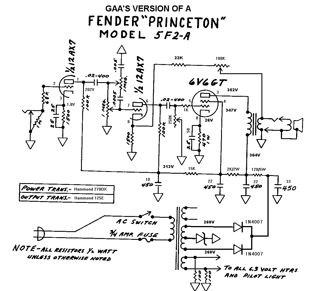
Plate voltage is 352V.
Cathode voltage is 26V, so current is (26/470) = 55mA.
There is about 8.5mA on the 2K/2W screen resistor.
After subtracting the 12AX7 plate current the 6V6 screen current is about 6mA.
The 6V6 is dissipating about (352-26)*(26/470 - .006) = 16.1 Watts.
That's high based on the 6V6 datasheet, but pretty common for modern single-ended 6V6 guitar amps.
Views
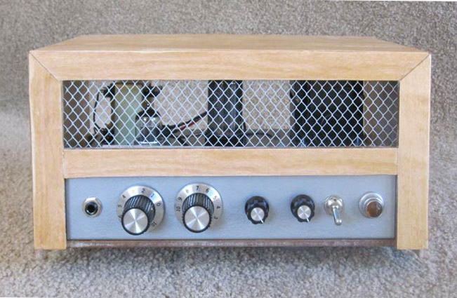
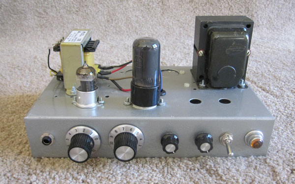
Below is a front view. The chassis is a Hammond 10x6x2 steel chassis spray painted with a hammertone finish. From left to right on the front panel are the input jack, volume, tone, master volume, Negative Feedback control, power switch and indicator light. On top are the OT, the 12AX7, the 6V6 and the PT. The chassis has a few extra hole because I've used it in other projects.
The amp originally had a standby switch on the front (I was worried about the SS diodes bringing up the B+ too quickly) and the Negative Feedback control on the back. Prevailing internet wisdom says that a standby switch is unnecessary so I scrapped the standby switch and moved the Negative Feedback contol to the front panel in it's place. It makes more sense to have all the controls where you can get to them even if you don't use them often.
The Master Volume and Negative Feedback have mini-knobs since I don't use them much and tend to keep them dimed (i.e. normal volume and normal feedback).
Below is the back side. From left to right you see the fuse, AC jack and speaker jack along with more extra holes.
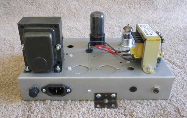
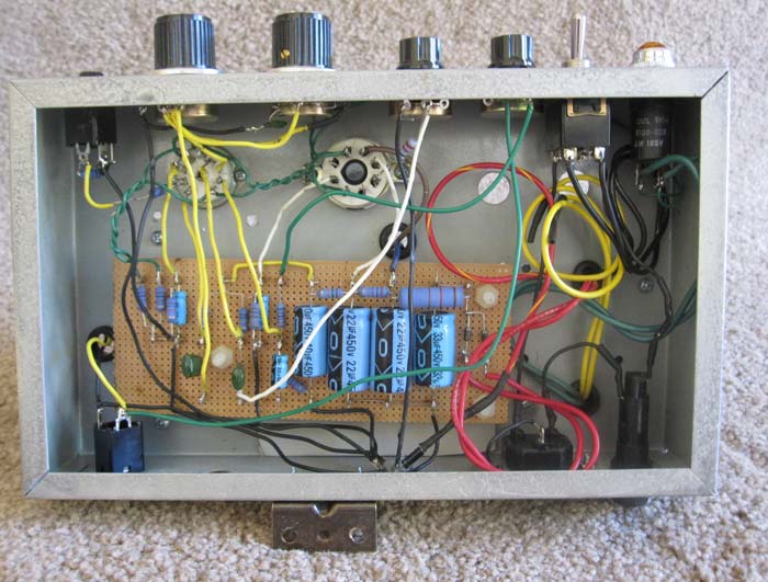
Here's the underside. Eliminating the rectifier tube and building the amp as a head made the layout very compact. As an experiment I used Vectorboard to mount the components. It made assembly quick and easy. Vectorboard is okay for a light duty amp. I wouldn't recommend it if you plan to do lots of mods.
Variable Negative Feedback
The variable negative feedback was an interesting experiment. Decrease the feedback and the sound "loosens up" - it gets louder and brighter, the bass is reduced and it distorts more easily. With the feedback enabled you get a cleaner, more hi-fi sound.
Originally I had a 4.7K resistor in series with the 100K pot. That allowed me to dial in more than normal feedback. With that setup the feedback effect is much more pronounced. With 4.7K of feedback the sound is clean, but not very loud which is not very useful for a guitar amp.
The amp sounds good with the stock 22K feedback resistor. I ended up putting a 22K in series with the 100K pot so when the feedback control is dimed at 0 ohms I get the stock feedback. If you really like tweaking the feedback use a 12K in series. In my opinion using a potentiometer for the feedback control is overkill. A simple on/off switch with 22K of feedback is sufficient.
You really need a tone control if you open up the feedback loop otherwise the amp is way too bright.
Master Volume
The Master Volume was also an interesting experiment.
If you set it to 10 it's equivalent to having the original fixed resistor in the circuit.
Turn the master volume down and crank the volume and you'll get preamp distortion at low volume.
If I were to use it more often I'd replace the linear pot with an audio taper pot since the
useful settings are near the end of the range.
6L6 Substitution
I tried a couple of very old 6L6s in place of the new 6V6.
The 6L6 requires 0.9 amp of heater current versus 0.45 for the 6V6. The PT was rated for 3A at 6.3V so it could easily handle the 6L6, 12AX7 (300mA) and pilot light (~300mA). I changed the OT impedance from about 6K for the 6V6 to 3K for the 6L6.
With the existing 470 ohm cathode resistor the cathode voltage was 25.5V. Plate was 354V. Dissipation was about 17W. That's probably a little low for a 6L6. I could have used a smaller cathode resistor.
It sounded pretty similar to the 6V6 - maybe a little louder and one tube, an RCA, seemed like it had slightly smoother distortion.
Unfortunately I didn't consider 6L6s when I built the cabinet.
The cabinet has enough clearance for a 6V6 but it is too small for the taller 6L6.
Do It Yourself
Here is the Bill of Materials. The BOM includes Mouser Part numbers and prices circa 1999. The BOM is also available in the form of a spreadsheet. Click here for an Excel spreadsheet compressed into a ZIP file.
Links
Feel free to contact me if you have any questions or comments. My other DIY amp page can be found here
Updates:
5/16/01 - added schematic
2/06/02 - added BOM
4/10/06 - moved to new server
2/22/07 - added Runoffgroove link
11/07/09 - fixed bad links
06/25/11 - Put new pictures and schematic on main page